Full Wave Rectifier Schematic Full Wave Rectifier Graph
Rectifier wave circuit full theory capacitor working load rl voltage do bridge diagram calculate output half dc its types Full wave rectifier graph Full wave rectifier schematic
Full Wave Bridge Rectifier Circuit Convert Ac Voltage To Dc Pcb Designs
Full wave rectifier schematic In-depth guide to full wave rectifier Rectifier circuit diagram rectification diode operation connected shown below
With the help of neat circuit diagram explain working full wave
Rectifier waveformThe full-wave bridge rectifier What is full wave rectifier circuit diagram working advantagesFull wave rectifier diagram ncert.
Full wave rectifier basics, circuit, working & applicationsSchematic diagram of full wave rectifier Full wave rectifier circuit working and theoryFull wave rectifier schematic.
![Full Wave Rectifier Graph](https://i2.wp.com/www.vedantu.com/question-sets/69a45f3a-74bb-4e58-bc55-f923ddf329963699996288789239680.png)
Full wave bridge rectifier schematic
Full wave rectifier graphRectifier circuit diagram Full wave rectifier graphWhat is the function of rectifier cheaper than retail price> buy.
Full wave bridge rectifier circuit diagramFull wave rectifier: working principle, diagram, and formula What is half wave and full wave rectifier?Full wave bridge rectifier circuit convert ac voltage to dc pcb designs.
![Full Wave Bridge Rectifier Circuit Convert Ac Voltage To Dc Pcb Designs](https://i2.wp.com/circuitglobe.com/wp-content/uploads/2015/12/FULL-WAVE-BRIDGE-RECTIFIER-FIG-5-compressor.jpg)
In-depth guide to full wave rectifier
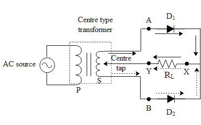
Schematic structure of the full-wave rectifier under study. .
.
![Full Wave Rectifier Graph](https://i2.wp.com/www.tutoroot.com/blog/wp-content/uploads/2023/03/e2.png)
![Full Wave Rectifier: Working Principle, Diagram, and Formula](https://i2.wp.com/images.collegedunia.com/public/image/4f25366ea1390ff42eb39c91b52dc4ed.gif?tr=w-344,h-339,c-force)
![In-Depth Guide to Full Wave Rectifier - Circuit Diagram, Waveform](https://i2.wp.com/www.tutoroot.com/blog/wp-content/uploads/2023/03/e2-300x300.png)
![Full Wave Rectifier Schematic](https://1.bp.blogspot.com/-uzWX38U8Hjs/YO60pnoF8UI/AAAAAAAABM8/otQyNJpK8PIUk9vmeOwTroo0cMf9xL06ACLcBGAsYHQ/s16000/Full%2BWave%2BBridge%2BRectifier%2BCircuit%2BDiagram.png)
![Full Wave Rectifier Circuit Working and Theory](https://i2.wp.com/www.elprocus.com/wp-content/uploads/2015/01/21.jpg)
![テスト ヤフオク! - WE 412A FULL WAVE RECTIFIER 1 PCS MINT テスト](https://i2.wp.com/www.elprocus.com/wp-content/uploads/2015/01/21-300x223.jpg)
![Full Wave Rectifier Graph](https://i2.wp.com/www.electroduino.com/wp-content/uploads/2021/04/What-is-Full-Wave-Rectifier-Working-Principle-Circuit-Diagram-Waveforms.jpg)
![The Full-Wave Bridge Rectifier - Last Minute Engineers](https://i2.wp.com/lastminuteengineers.b-cdn.net/wp-content/uploads/2020/02/Fullwave-Bridge-Rectifier.png)
![Schematic structure of the full-wave rectifier under study. | Download](https://i2.wp.com/www.researchgate.net/profile/Ping_Li58/publication/262771370/figure/download/fig1/AS:614309948313609@1523474313391/Schematic-structure-of-the-full-wave-rectifier-under-study.png)
![Rectifier Circuit Diagram | Half Wave, Full Wave, Bridge - ETechnoG](https://1.bp.blogspot.com/-bTCLeh50vOE/YO6z8d2H3zI/AAAAAAAABMs/w7vO2Gw8nTcJVMMKq1r3cBeyP8caaUywwCLcBGAsYHQ/s16000/Half%2BWave%2BRectifier%2BCircuit%2BDiagram.png)